To Infinity and Beyond - Becoming a Better DopeyBadger (Comments Welcome)

Marty and Mike Wazowski - Laugh Canister Part 2 - Lighting
Now that the base construction of the laugh canister was complete, it was time to move to the lighting.

7ae6b-monstersincscreenshotgroup01.jpg


The laugh canister has one place for an obvious light. The capacity indicator. So that seemed like the most logical place to attempt to put one. For those that have followed along in previous projects, when we've attacked the item of light in the past we've used LEDs wired to a battery (like the Scarlet Witch headpiece), LEDs in a single battery set (like the Maui Hook), and EL wire (like the Ms Marvel shirt and Shang-Chi rings). But each time, these items left something to be desired. The LEDs were alright, but were sparse and not bright enough for my taste. They were noticeably "on" in the dark in pictures, but less noticeable when active in the races. The EL wire was more continuous, but again it just didn't light up and make it known we were using lights like I wanted. So I wanted to try something new this time around.

For comparison, here is the EL wire we used for the Shang-Chi rings.

thumbnail_IMG_5717.jpg

Admittedly a good option for what we needed it for. It was very flexible and could be wrapped around the rings. Additionally the battery pack was two AAs and had a belt hook on it which made it easy to attach to the top of my arm. Now, we were ready to step into the big boy ring with a new LED strip.

thumbnail_IMG_5718.jpg

This is an Adafruit Flexible LED Strip - 352 LEDs per meter - 1m long - Red (link). That's roughly a little more than 100 LEDs per foot, or like 8 LEDs per inch. It's super dense with LEDs. Which means it's super bright. Maybe... actually... a bit too bright.... We'll get to that though at a later time... For now though, this is the strip I was going for this time. I don't think anyone will mistake whether this is illuminated or not. For a final comparison, this is both the EL wire and 352/m LED strip on at the same time.

thumbnail_IMG_5719.jpg

Yea, it's not really a comparison. The 352/m LED uses a single 8 AA battery pack to illuminate it. I went with this one (link) from Adafruit. It has an on/off switch as well as a plug. So by using this female DC power adapter (link) I could very easily connect the batteries to the LED strip. No soldering needed. The LED strip can be cut to size. Every few inches there are black markings which make for a cut line. At these points it has exposed connections such that if you cut there you can easily solder new wires to the same location.

thumbnail_IMG_5716.jpg

In addition to the battery pack, female adapter, and LED strip I ordered a small screwdriver. This would be easily portable in the event of problems on the trip (link).

Next up was determining the length of the LED strip. G wanted it as long as I was willing to make it. She wanted it to stand out. So we diverged from the official proportions a little to stretch the lights out. Once we determined how long the lights were going to be I drilled a small hole at the bottom of the section where the lights would be to string the wire through.

thumbnail_IMG_5720.jpg

I put the lights through, lined up the lights opposite the handle on the opposite side, and then taped it down with the provided backing. But it became pretty clear that wasn't going to be good enough. So I put down a layer of Barge All Purpose Cement (link). I've used this cement for several projects, but if you're new around here be aware that this glue is super duper strong. So be mindful when you work with it to avoid putting it on your skin. If you do, use make-up wipes to help remove the glue. The LEDs weren't going anywhere after the cement.

thumbnail_IMG_5721.jpg

Looking good! But maybe too good...

thumbnail_IMG_5736.jpg

This is what it legit looks like in a dark room. It illuminates everything, and this is just a small 7 inch LED strip from the 3.2 ft strip. The 8-AAs are needed for the voltage, but there may be other options to illuminate it that may dull it a bit.

thumbnail_IMG_5738.jpg

With that, we move into the new frontier: Sound!

Next up - Sound!
 
Last edited:
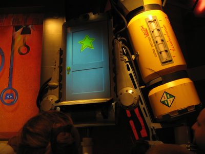
Marty and Mike Wazowski - Laugh Canister Part 3 - Sound!

Alright, full disclosure, I had/have no idea what I'm doing on this part. This is all new. So with that I'm going to include not just the path to how it works, but the full process I went through. Which means lots and lots and lots of troubleshooting. To the point that I was several hours into troubleshooting and almost gave up. I'm not an electrical engineer, and these things are designed by Adafruit to be user friendly, but there's a lot that can go wrong. So with that let's dive into sound engineering.

thumbnail_IMG_5727.jpg

Let's cover the components:

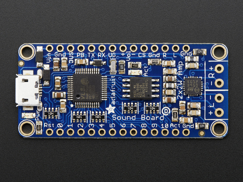
1 x Adafruit Audio FX Sound Board + 2x2W Amp - WAV/OGG Trigger -16MB (link)
1 x Speaker - 3" Diameter - 4 Ohm 3 Watt (link)
1 x 3 x AA Battery Holder with On/Off Switch, JST, and Belt Clip (link)

Not much to it. The Adafruit sound board includes an Amp on board so that makes things easier. This PDF was a super helpful tutorial (link). It didn't cover everything, but it covered most of the basics necessary to get it to work.

First up was choosing some audio to use. The most obvious sound was the classic joke sound "Ba-dum-tss". I found this website called "Pixabay" which had tons of royalty free sound effects. So this is where I found most of the effects. In addition to the "Ba-dum-tss", we also went with two other sounds when the button was being pressed. These sound effects would occur in a normal non-random pattern. A sequence upon each press of the button.

1) Ba-dum-tss
2) A sound for powering up the device after hearing laughter
3) An air-hiss and "escaping" laughter from the canister

This would represent the totality of our "show". A joke, their laughter, and then our exit because the canister leaked and we needed to gather more laughs.

I wanted a verbal confirmation of the powering up of the device. So I found a website that would convert text to voice for free (Narakeet). You could get 20 free conversions before you had to start paying. I typed in "Laugh detected. Laugh detected" and then went through the different voice options. I had a preference, but the other members of the house thought it was less clear what exactly it was saying. So we went with something that was robot adjacent, but not too tough. If you want to hear for yourself what it sounds like, type in "Laugh detected" into Narakeet and choose option "Robovoice". I found the air hiss and laughter sounds on the "Pixabay" website.

I had the sounds, but for effects 2 and 3 I had multiple sounds that needed to be overlayed with each other so that it would be a single button push. To do this, I used Audacity which is a free to use sound program.

thumbnail_IMG_5725.jpg

I have limited use with Audacity in a work capacity when we were capturing sounds for analysis for my research. But I wouldn't call me an expert or even an intermediate user by any stretch of the imagination. I could however open one file, click and drag the second file on top of the other, and then save it as a single file. Wa-laa we've got them combined. Next up was taking the sounds from the computer and getting them onto and working on the sound board. But before we get there, we've got to get the sound board working!

thumbnail_IMG_5728.jpg

I'm a noob when it comes to electrical/sound engineering, and I really should buy a breadboard so that all my testing work is up off the benchtop. But for now, I'll stay a noob and do my work the dirty way. I cut off the end of the battery pack wire which was in a nice plug form and exposed the red and black wires. The red wire connects to the "Vin" and the black wire connects to the "Gnd".

adafruit_products_2210-05.jpg


I turned on the battery pack, and hooray there was a small illuminated green LED. That means we've got power! Next up was connecting the pushbutton.

thumbnail_IMG_5729.jpg

The pushbutton itself has two connection points, and thankfully they're interchangeable. It doesn't matter which is connected to which pin. One of the points needs to be connected to the numerical pin (0 through 10), and the other needs to be connected to "Gnd". You can see another "Gnd" to the right of "Act" after the "10" pin. That's the one I used for the pushbutton. You could use any of the numerical pins for the button, but "0" will be the first searched, thus it will be the fastest to make sound upon depressing a button. But I could have chosen "5" or "7" instead. Just make sure you know which you've chosen so that you can properly name your files. To confirm it was working, I pressed the button down, and a red LED illuminated indicating a connection!

thumbnail_IMG_5731.jpg

Next up was connecting the speaker. The speaker I chose does have a positive and negative connection point on the underside. So I had to make sure that red was positive and black was negative.

thumbnail_IMG_5732.jpg

These were connected to the speaker, and then to the sound board where it says "- R +" on the vertical axis of this picture. I did confirm before purchasing this sound board that it is possible to run this with only one speaker (mono) and two speakers (stereo) was not necessary.

Now it was time to load some sound effects onto the board! Here came the first real hiccup!

thumbnail_IMG_5722.jpg

I plugged in the micro USB to the sound board, and then connected that to a USB to lightning converter which plugged into my Macbooks lighting port. And... nothing. The board was illuminated green, but nothing was happening on the laptop. I thought it should come up as a USB drive, but it didn't. So I thought maybe I got a dud. We pulled out a second cord and tried again, and... nothing. Now I was getting a bit disappointed. Was our journey of sound over before it even really started? I did some googeling and found that some USB cords are only meant for charging and can't do data transfers. So I grabbed a ton of different cords and kept trying to find the right size hoping one was a data transfer cord. And after several attempts... success! I found a USB cord that worked! Huzzah!

thumbnail_IMG_5723.jpg

The sound board showed up as a USB drive labeled "ADAFRUITFX" and came preloaded with a sound on it. The files need to be in .ogg or .wav format, so I made sure to save my Audacity files in .ogg format. The .wav file is better, but I started with .ogg. The naming convention is such that it is labeled Tnn.ogg or Tnn.wav. The "nn" is the pin you selected for the pushbutton with a leading "0" if it's anything but "10". So since I was going with pin "0", then I put "T00" as my file name. With this destination, the board would recognize this single sound effect should be played every time the button "0" is pushed. There are other naming conventions available such as "Random", "Hold", "Next", and "Latch" but for testing that it worked, I just went with something simple.

So I loaded my file onto the board. I then disconnected the board from the computer's lightning port. This is an important step. The board can't be hooked up to the computer and make sound from the button pushing. So if you're not getting a response from the board, make sure you're not still plugged in. However, I learned after several hours of troubleshooting (we're getting there) that you can leave the board plugged into the micro-USB as long as it's not connected to the computer. Since the board felt fragile, it was good to learn I didn't have to keep plugging and unplugging from its port to test it out.

And with that, G and I headed back to the sound board, battery, speaker and button setup and pushed the button. And the moment of truth... it said... "Right". Huh? Was I hearing that right? Was it really saying "right"? Why was it saying "right"? Why not "ba-dum-tss"? It was making sound, but not the right sound. That led me down a path of googleing trying to figure out why it was saying "right" and you know what, it was no where to be found. Nothing explained to me why it was saying the word "right". After some time passed, I was watching a Youtube video of a different person using this board and setting it up. He got to this step, but he hadn't preloaded any sound onto it yet, and then when he tested his system he heard, "Right". And right then is when it dawned on me. It's saying "right" because it's the right speaker, but it doesn't recognize the audio file. So the system is working, but something is wrong with my audio file. But what's wrong? It's got the right name. It's got the right file extension (.ogg or .wav). What's wrong with it? Is it copyright protected in some way? Was something in Audacity to blame?

In the instructions is a downloadable zip file that contains a bunch of test sounds. So I deleted my sound effect and loaded those on. I touched the button to each of the 11 pins and confirmed through the test sounds that the board was working. So that let me know it was a me issue, and not a board issue. It could recognize their sound effects, just not the one I made.

After several hours and several Youtube videos of monkeying around, I found a snippet at the bottom of the instructions talking about the KHz and bit rate, and stereo vs mono.

"The absolute biggest files you can generate and play are CD quality uncompressed stereo WAV files, at 44.KHz/16 bit. Stereo WAV 44.1 KHz 16 Bit - (2 bytes * 2 channels * 44100) = ~175 KB per second, so 2MB can hold 12 seconds, 16MB can hold 90 seconds Mono WAV 44.1 KHz 16 Bit - (2 bytes * 1 channels * 44100) = ~88 KB per second, so 2MB can hold 23 seconds, 16MB can hold 180 seconds (3 minutes) Stereo WAV 22 KHz 16 Bit - (2 bytes * 2 channels * 22050) = ~88 KB per second, so 2MB can hold 23 seconds, 16MB can hold 180 seconds (3 minutes) Mono WAV 22 KHz 16 Bit - (2 bytes * 1 channels * 22050) = ~44 KB per second, so 2MB can hold 45 seconds, 16MB can hold 6 minutes Stereo WAV 11 KHz 16 Bit - (2 bytes * 2 channels * 11025) = ~44 KB per second, so 2MB can hold 45 seconds, 16MB can hold 6 minutes Mono WAV 11 KHz 16 Bit - (2 bytes * 1 channels * 11025) = ~22 KB per second, so 2MB can hold 90 seconds, 16MB can hold 12 minutes"

-Adafruit PDF instructions linked earlier

That's all to say, it wasn't as simple as grabbing the sounds from the internet and converting them to a .ogg or .wav file. They needed to be a specific format as well. So back to Audacity I went and mucked around trying to get the files converted to meet the above specifications. I'd make a change, load it to the board, and "Right". I'd make another change, load it to the board, and "RIGHT". I'd make another change, load it to the board, and "RIGHT". I'd make another change, load it to the board, and "RIGHT".

RIGHT
RIGHT
RIGHT
RIGHT


Needless to say, I was getting VERY frustrated. I spent hours making changes and over and over and over it failed to work. I read forum posts. I watched Youtube videos. Everything. And then I found a section of the PDF instructions talking about an alternative website to use for converting the files instead of Audacity. This free to use site (link) also did conversions of mp3 to ogg or wav files. It also let you choose bit rate and KHz. So I converted my "ba-dum-tss" mp3 sound effect into a 8000 Hz mono .ogg file. I loaded it on to my sound board with the file name "T00.ogg" and... and... and... "BA-DUM-TSS"!!! It worked. Oh man, I can't describe to you how elated I was when that worked. I was honestly so close to throwing in the towel on this one. But I'm glad I didn't.

With the sound effect working, it was time to load the other two sound effects. Since I wanted all the sound effects to play in order from a single button (pushed three separate times) I was going to use the "Next" feature. So I named my files "T00NEXT0", "T00NEXT1" and "T00NEXT2". You must start with "NEXT0" otherwise it won't see the other files. I loaded them onto my computer, and... "RIGHT".

You've got to be kidding me!
Alright, so "Ba-Dum-Tss" worked by itself, but not with the others. So I reloaded each sound individually and could get each to work on their own, but when I put them together, no luck.

thumbnail_IMG_5724.jpg


Why, why, why, why? Clearly something with the naming convention, right? So this sent me down another few hours searching for any tips I could find in the Adafruit forums. And finally after a long search I came upon a little tidbit that was seemingly unrelated to me, but possibly useful. Sometimes, but not all the time, the sound board can get confused by what is in your laptop/computer's recycling/trash. If you have old files in there, despite them not being connected to the sound board in anyway, it apparently is capturing those in it's directory or something and when it comes time to read "T00NEXT0" it gets confused. So when you upload your files, make sure to empty your recycling/trash as well on the laptop itself. This will make the board not confused, apparently. So with that, I did that, I plugged it in, I pressed the button, and...

It worked! All three sound effects with three pushes of the button. Man, G and I were jumping for joy on that one. I quickly disconnected the sound board from anything, and then prayed it'll stay working from here on out. It sounds great. The audio volume is good. Not too loud and not too quiet. I put finishing the sound on the back burner, because now we get into the fun foam part!

Next up - Foam construction Part 1!
 
Last edited:


I hope you have some really good plans to transport this safely in your checked baggage......all I can think is what TSA would make of a cylinder stuffed with electronics.

But aside from that small detail, it's looking great!

I've thought about it. The 8 AA battery pack will be disconnected and the other battery pack will be empty. So there won't be a lot going on in there outside of a speaker, empty battery pack, sound board, button, and some wires. I'll leave the one side open so they can easily look in it if they so desired. It might fit in a backpack and thus could be in my carry-on then. I haven't tested that out yet though.


im-watching-watch-you.gif
 
Marty and Mike Wazowski - Laugh Canister Part 4 - Foam construction Part 1!

I feel like foam construction is when things really start to take shape. It goes from theoretical to, "oh that's what it's suppose to look like."

For previous projects (Scarlet Witch headdress, Ms Marvel fist, Shang-Chi ten rings, and Maui's hook), I used Plasatazote foam (link). This foam is useful because it is translucent, which was useful in each of those projects. But for the laugh canister, it wasn't necessary to work with translucent foam since the light was going to be intentionally exposed as the canister indicator. So this time around I was going to work with some regular cosplay foam. I had my choices of 2mm to 8mm thickness for this project. I went with the 2mm thickness because of how difficult it was to wrap the translucent foam in 4mm or 8mm thickness into a curved shaped. But since I don't have any experience with regular foam, I wasn't sure whether that was the right choice. I went with this cosplay 2mm foam (link).

thumbnail_IMG_5741.jpg

For the foam, G and discussed that since we extended the light a little more than the proportions from the image, we needed to cut a little bit of space from somewhere else. The button has to be in what I'm calling the "clasp" section of the canister. When the canister is hooked up to a door, there are two places where claps hold it in place (they're black in color). For those to have a slightly different appearance from the rest of the canister, G and I decided to leave those as bare PVC. So since the button was falling in the bare PVC spot colored black, it meant we were kind of defined on the top side as to how large the top rim would be 2.5 inches. However, we had more flexibility with the bottom. But again since we stretched the lights, we lost some space. And I needed to leave a little room for the "-" symbol, so we ended up making the bottom rim 2 inches instead. I confirmed G was ok with this slight difference in size between top and bottom and she was good with it. Funny enough she forgot about that a few minutes later once I got things glued down and was like, "hey, we made them not the same size, it looks funny." I just rolled my eyes at her and explained we already discussed this and the reasoning we had for it. After going through it again, she was in agreement with the plan again. So I measured the first top rim piece at 2.5 inches, and then measured the circumference of the PVC pipe using a soft tape measure. It came in at 14.25 inches. I cut the foam using a standard X-acto knife.

thumbnail_IMG_5742.jpg

Using same knowledge gained from the Ms Marvel bracelet, we found some rubber bands to help hold the foam in place while the Barge All-Purpose cement would dry. Once we were all set, we went ahead and put a layer of cement on the foam. Interestingly enough, the foam came in a wrapped cylinder shape, so the cut pieces had a natural curvature to them. But when the cement was placed on the foam it straightened out. I don't really know why, but it was interesting to note. I also placed a layer of cement on the PVC itself, and then I wrapped the foam around the PVC. The goal was to get the seam of the foam (where the two ends would meet) to always be on the back side by the handle. This would maintain a clean appearance in the front. But when I finished wrapping the foam to the PVC it became apparent that the foam has a little stretch to it. Because pre-cement the foam wrapped perfectly at 14.25 inches. But after the cement and placement, there was a small piece of extra foam left over.

thumbnail_IMG_5743.jpg

This came in at about 0.125 inches. So I took this into account for future measurements and reduced the soft tape measured distance by about 0.125 inches and was hitting the seam about even on the wrap job.

One other thing to note, the foam did REALLY well at holding it's shape. So well that the cement essentially held it in a permenant place almost immediately upon coming in contact with the cement on the PVC pipe. I didn't end up needing to use the rubber bands. So this was a nice surprise. The downside though was that you really had to make sure you had it placed exactly as you wanted it, because it very quickly became hard to change after it came in contact.

The top rim and bottom rim were the easy foam pieces. The middle was harder. The middle needed a section cut-out for the light, as well as the back side needed to take the handle into consideration. So there was a lot of measuring, and re-measuring, and trying to line everything up. G and I decided on leaving about a 1.5 inch viewing window for the light on the front, and then we made little cut-outs for the handle.

IMG_5744.jpg

This left us with this:

IMG_5745.jpg

It was a good start. The light came in at about 8mm in height. So with each layer of foam coming in at 2mm, we needed to do at least 4 layers of foam before we'd exceed the height of the light. This would enable us to put a casing around the light if we chose to do so. So I repeated the process three more times. This is the moment where I second guessed whether having the foam come in at 2mm instead of 4mm was a good choice. But in hindset at the completion of the project, I still think the 2mm foam size was the right one. It was much easier to work with than previous foam projects, and I think the thicker sizes may have been more troublesome.

The extra 0.125 inches of foam was an issue, but I ended up using a dremel tip to shave it down. Since we were doing four layers, then this would be hidden and never seen by anyone anyways. So I wasn't terribly concerned about the neatness of these bottom layers. I'd clean things up later.

After putting down four layers of foam, I was left with this on the back side:

thumbnail_IMG_5746.jpg

Steph didn't think it looked that bad, but I wasn't pleased with it. It looked messy to me. So I cut out some foam pieces and placed them over the seam. I tried to emulate a welded on piece of metal that was holding the handle in place. So I made some "screw holes" using the Dremel circular sanding attachment in a vertical direction. Normally that piece is to be used horizontally to sand things down, but it has an interesting groove pattern on the top. So when you hold it vertically it can make it appear as there is a screw in the foam.

thumbnail_IMG_5748.jpg

I felt like this looked better that the messy seam I had earlier. Steph thought I was overthinking it.

I went around the edges of the "clasp" area and evened things out. This gave it a cleaner appearance. Here were some pictures of the front of the canister after the four layers of 2mm foam and cleaning up the edges.

IMG_5747.jpg

IMG_5749.jpg

IMG_5750.jpg

At this point, we were pleased with the depth differences that the canister was giving us between the "clasp" area and the other foam constructed areas. Next up was figuring out how to wrap the beveled edge in foam.

Next - Foam construction Part 2!
 
Last edited:


Marty and Mike Wazowski - Laugh Canister Part 5 - Foam construction Part 2!!

Alright, onto the beveled edge foam.

thumbnail_IMG_5752.jpg

As you can see on this close-up we've now got a good thing going for the four layers of foam around the top rim. So now it was all about trying to bridge the gap on the beveled edge at the very top. I pondered over this one for a bit. How would I make a piece of foam that would fill this space appropriately. I wasn't a normal shape per se. It was an angled piece of foam that needed to have either different depths of the top and bottom of the foam needed to be different lengths. But how could I make a single piece of foam have a top and bottom of different lengths with a gradient depth.

At first, I tried to cut out a piece of foam that covered the 15 inch diameter. I went with a 4mm translucent piece so I wouldn't have to do this several times (like with the 2mm foam). I lined up the piece that was 15 inches long and about 0.25 in tall with no luck. It didn't fit right. So then I shaved some of it down on the top side of it at an angle such that one end of the 0.25 in width was thick and the other was thin. But this didn't work either. So I was back to the drawing board. How do I make a shape that has two different circumferences to match the circumference of the bottom of the ring and the top of the ring? And when I proposed the question in that manner, I had my answer. I needed to make a concentric circle design, or a ring.

So I pulled out my ruler and measured the radius of the inner circle (the inside of the PVC pipe, and the outer circle (the edge of the second layer of foam in my four layer design on the top rim. I then used a compass to hit each of these radii in a circle on a piece of 4mm translucent foam.

IMG_5751.jpg

This was successful.

thumbnail_IMG_5753.jpg

This was very successful. It landed exactly as I wanted it to and covered both the top of that very top rim and up to the foam layers themselves. So all I needed to do was replicate this for the bottom beveled edge and I'd be done...

Oh *&^%&! I was an absolute idiot when it came to where I placed my circle on the last remaining piece of 4mm translucent foam I had available. So my remaining options were four layers of very precisely measured 2mm foam, use the 8mm foam, or ??? Needless to say, I wasn't pleased with myself. Usually I'm way more calculated in my decision making and this one was a major goof up. So I sat there for a good bit pondering how to solve this one. I cut out an 8mm ring but it was way too thick. I considered shaving it down with the dremel to get it to 4mm but knew I can never be even enough on it. So I was in a pinch. Then, eureka. What about doing two half moon shapes. Not a complete ring so I don't have enough space for the full circle, but instead there was enough space to do two half moon shapes next to each other. It wouldn't be perfect, but since it was going to be covered by a layer of 2mm foam it didn't have to be. And thankfully the plan worked.

IMG_5754.jpg

After that I cut out a ring of the 2mm foam and I was done. Or so I thought. I ended up cutting about 8 different rings to get the coverage just right. Let me tell you, the compass measurement needs to be darn near exact for the small 2mm foam to fit properly. I'm talking a small error of 1-2mm in either direction was enough to completely throw off being able to use the ring. So I wasted a lot of 2mm foam trying to get the rings just right. But since these were going to be visible, they needed to be on point.

thumbnail_IMG_5755.jpg

Ultimately, after several attempts I ended up with something I was pleased with. So I cemented it down, and then I made my way onto the next phase of the foam construction. The casing around the light!

Next up - Foam construction Part 3!!!
 
Last edited:
Marty and Mike Wazowski - Laugh Canister Part 6 - Foam construction Part 3!!

Now that the base of the foam was finished, it was time to add some finishing touches to the casing around the light. I needed to make the capacity indicator look legit.

The first thing I did was paint the inside of the casing around the light in black. I used my Liquitex BASICS Acrylic paint set (link). I have been very pleased with this set of paint and how far it's gotten me. We're on our fifth cosplay project and there's still a bunch of colors untouched and nothing is out yet. So it's a really good starter set of paints for a cosplay hobbiest. For the black, I went with Mars Black.

thumbnail_IMG_5756.jpg

I felt like this would help better define the area around the indicator light. Really help make it stand out. This was bare PVC pipe alongside the indicator light, so it had a nice natural shine to it as well.

Next up was something new, and I felt like it would take the canister to the next level. A plastic sheet for the casing material.

IMG_5757.jpg

I bought this simple piece of plastic at Home Depot (link) and a plastic cutter tool that was recommended on the Home Depot website (link). I watched the tutorial on Home Depot's website on how to properly cut the plastic which seemed rather straightforward. You score the plastic where you want to break it several times over with the plastic cutter tool, and then you hold the plastic over the edge of a table and snap it off. Seems like some people online had issues with this, but it was pretty simple for me on my one and only attempt. I ended up cutting the piece of plastic to be just barely as wide as the hole we had made and about an inch of extra space on the top/bottom for a place to cement it down. Here's the thing. The PVC pipe is curved. The plastic is most definitely not curved. It's actually extremely rigid and didn't want to be anything but straight. So I wanted to minimize the space at which the PVC pipe would curve away from the plastic. I figured I would need to place a piece of foam over the plastic anyways, so I tried to go as small width wise as I could. I also tested the plastic over the light just to make sure there wasn't any weird distortion effects (which there wasn't).

IMG_5758.jpg

So I cement glued the plastic down. Unlike the 2mm foam, this was something I had to hold in place for a little bit just to keep it from moving. I tried to press pretty hard to try and dampen the distance of the curvature as much as possible.

I then cut out a piece of foam that had an extra two inches on either side of the end of the plastic. The hope was that the foam would add a layer of extra support and "hold down" the plastic in case it wanted to move a bit despite the cement.

IMG_5759.jpg

This piece went through two iterations. I wanted some tick marks around the capacity indicator light. The first iteration (not pictured) had smaller ticks, but they looked too puny. So I remade it again, and made the ticks about 2-3x as big. This felt like a good size. I overlayed it over the indicator light just to get a feel for what it would look like.

IMG_5760.jpg

It looked pretty good to me. Not big enough that it covered the light in any way, but big enough that you could see they were there. So then I cement it down.

IMG_5761.jpg

The stretchiness characteristic of the foam paid off here. Because it worked more like clay when I was molding it around the plastic casing. It actually allowed me to get some pretty distinct edges, while also providing that support for the plastic I was looking for.

Then, to better replicate the look of the canister, I added small "+" and "-" symbols to the top and bottom of the indicator.

IMG_5762.jpg

Lastly, I added some screw embellishments (again using the dremel sanding attachment in a vertical manner) to make it look like the front plate had been screwed over the indicator housing.

thumbnail_IMG_5763.jpg

And with that, we were done with the foam construction! If the foam construction allowed the canister to take shape, then the paint was going to bring it to life!

Next up - Painting!
 
Marty and Mike Wazowski - Laugh Canister Part 7 - Painting!

Time to bring the laugh canister to life!

IMG_5765.jpg

For this project, I was using three different colors (Cadmium Yellow Medium Hue, Silver, and Mars Black). Of the yellows we had available (of which we had about 6-7 choices) G and I felt like this yellow was the closest representation of the laugh canister color.

In past projects we've used Flexbond as a primer (link). It allows the foam to stay flexible despite being painted and helps reduce cracking in the paint where there's movement. It also acts as a primer which means you end up using less paint to cover the same surface area. But this project didn't end up needing it. Unlike the translucent foam which has porous gaps in it that allow light to pass through this foam is quite dense. So the paint sits atop it and doesn't soak in. So where the translucent foam feels like it really needs the primer (and trust me I tried painting something without it once and it just soaked everything up) this normal foam doesn't have to have it if it's mostly immobile. And since the canister doesn't have any moving parts, I felt good about not using the Flexbond.

I started with the yellow since I wasn't sure how many coats it would take.

IMG_5766.jpg

It was slow going, and it took several passes on a single coat of yellow paint to get a good cohesive color. The black definitely covered better.

IMG_5767.jpg


This was after a single coat of paint of each color (yellow, black and silver). The yellow and silver absolutely needed a second coat of paint. The black only needed a few touchups. It was important to note that the yellow had no capability of covering up the black paint. With some colors you can make minor errors disappear with another coat of paint. That wasn't the case here with the yellow. Once it was on there, it was on there. So I wish I had known that before and I probably would have been a touch more careful when using the black paint. Here's the canister after two coats of yellow/silver.

IMG_5769.jpg

This is where it really started to feel cohesive. I painted the inside of the screws black and then the screw tops silver. Just to have some stark contrast to really make the screws pop. I considered doing some outlines in black on the plates, or on the casing, but Steph gave a hard no on those. She felt like the coloring of it was near perfect and it would be a mistake to outline those things. And since black was irreversible on this project, well then I wasn't about to find out what it looked like otherwise.

Now here's where a debate came up. G and I had discussed the codename of our laugh canister (Gathering Intact Giggles Instrument) and considered placing it on it. We also considered putting the units of the laugh canister on it as well (Gigglewatts). The debate was about the direction of the text. Since the black was permanent, this was a once and final decision. No take-backs. So I tested out writing the text on several scrap pieces of foam just to see what it would look like, and how small I could legibly write in paint. I used a pencil dipped in black paint to be as precise as I could be.

IMG_5770.jpg

So above you can see the canister codename spelled out in acronym form (looks like someone might have caught on, right @The Expert :thumbsup2
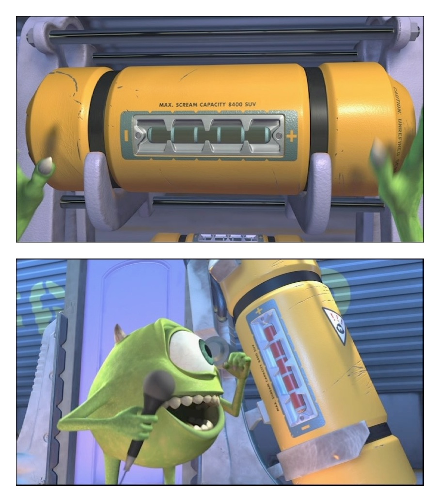
) as well as "Gigglewatts". The question was,

"If G.I.G.I is spelled on the left side of the indicator and vertically such that the first G starts at the "-" sign and goes upwards and the last I ends at the "+" sign, then what direction does Gigglewatts go in if it is on the right side of the indicator? Does it have the Giggle start at the "-" sign in the same direction as G.I.G.I or does it start at the "+" sign and go downwards?"

To me, they should both start at "-" and go upwards. But to Steph and G, they thought they should go opposite (G.I.G.I goes upwards and Gigglewatts goes downwards). To me, I felt like you would only turn your head once and you'd be able to properly read both sets of words. To them, it felt like Gigglewatts would be read backwards and was confusing. I polled my MIL, and several people at work as well. The split seems to be about 50/50. Half agree with me, and half agree with Steph. So what do you think? At this point, if there's this much disagreement, I'm leaning strongly towards not putting any lettering on it. At this point it looks very clean, and the wording might muck it up a bit too much. Plus, if there's controversy about which direction the wording should go, it's not worth having it on there to me. But what do you all think?

As we almost came to the end of the painting now, it was time to paint the top and bottom of the canister as well. To this point the canister has just been a single 2ft x 4 inch diameter PVC pipe cut to size. The nice part of the PVC choice was that there are natural pieces that fit on the PVC pipe that could be useful for caps. I looked at a few different options. Some were quite pricey and others pretty cheap. I was looking for something that would be functional. So a shower drain made a lot of sense for the top. This way it had a nice speaker like appearance for where the actual speaker would be hidden underneath. The bottom was just a simple end cap. The shower drain will house the speaker on the top, and has a pretty snug fit. So I don't think I'm going to have to do anything special to hold it in place. The bottom piece, I'm hoping to attach the 8 AA battery holder to it to hold it in place (haven't gotten that far yet). So the extra weight of the 8 AA battery holder may force it loose when running with it. So I'm tossing around some ideas, but that's yet to occur at this point. Here's what the top and bottom caps look like painted yellow.

IMG_5771.jpg

Lastly, on several occasions I've made mention of how bright the 352 LED/m strip really is. I'm not joking, it can be blindingly bright when looking at it. So much so, that I was slightly (maybe more than slightly) worried that if little 5 year old Timmy stared at it for too long while we were out and about that someone may attempt to bring a law suit against me because of it. Like so blindingly bright that when I was working with it a few nights ago and accidentally stared at it for about 10-15 seconds that the red bar of light was stuck in my vision for a good 10 minutes. I was seriously getting worried that I may have irreparably harmed my vision. So despite the LED looking good and no one would mistakenly not think it was illuminated, it was just too darn bright. But thankfully there was a potential fix. Instead of using 8 AA regular batteries which combine for about 12 volts power supply, I could use NiMh (Nickel Metal Hydride) rechargeable batteries which a combined 8 has a total voltage of 9.6 volts. This would make the LED less bright but still power it for a similar period of time.

thumbnail_IMG_5774.jpg

So here's the laugh canister with regular AAs:

IMG_5772.jpg

Make note of the illumination of red on the table. And then compare that to the rechargeable NiMh batteries.

thumbnail_IMG_5777.jpg

Still noticeably on, but not blindingly bright. You could stare at this without issue (not that you should). But a lot less likely to be an issue when standing in front of other people.

With that, we're up to date. The remaining things to accomplish are finalizing the audio equipment and soldering everything together, and then determining how to secure the inside components such that they're safe when I've got movement. Looking forward to wrapping this up, because I've got a sewing machine calling my name...

Next - Soldering the sound board
 
Last edited:
On a side note, Steph saw that Southwest airlines was having a sale on specific flights and may have booked us some flights to Disney World for October 18-23rd. She felt like these Mike and Marty Wazowski costumes were just too good to pass on attending a Halloween party in them. But let's be honest, she was just looking for an excuse for another Disney trip and felt like she may be able to sway me with this reasoning. I won't complain. These Wazowski costumes are going to get some use.
 
I'm leaning strongly towards not putting any lettering on it. At this point it looks very clean, and the wording might muck it up a bit too much.

I agree. The "real" canisters only have tiny lettering on it already, so putting both GIGI and Gigglewatts would overdo it. (love both tags though :)) It looks awesome nonetheless!

I would put the G.I.G.I. only if you guys really want the gag between you two, as I don't think anyone else will get it.
 
I hope you have some really good plans to transport this safely in your checked baggage......all I can think is what TSA would make of a cylinder stuffed with electronics.

I've thought about it. The 8 AA battery pack will be disconnected and the other battery pack will be empty. So there won't be a lot going on in there outside of a speaker, empty battery pack, sound board, button, and some wires. I'll leave the one side open so they can easily look in it if they so desired. It might fit in a backpack and thus could be in my carry-on then. I haven't tested that out yet though.


I was CERTAIN that TSA was going to pull the vest I made for my Electric Water Pageant costume. It was literally covered in wires and batteries and looked like a bomb vest when it wasn't turned on. I put it in my carry-on luggage and was fully prepared to pull it out and turn things on. It didn't even get pulled for a random check!

I'm not sure what may have happened if it was in checked baggage, but I didn't want to risk any delays or chance it not arriving, so I would advise carrying on if you can. I do that with anything that's not easily replaceable anyway.
 
Looks great!

In general, if you’re taking a poll, I would agree with you that they need to both face the same way - that way when the canister is on its side, they can both easily be read.

What about just putting ‘Gigglewatts’ next to the indicator and ‘G.I.G.I.’ around the rim where the Caution statement is on the original?
 
I agree. The "real" canisters only have tiny lettering on it already, so putting both GIGI and Gigglewatts would overdo it. (love both tags though :)) It looks awesome nonetheless!

I would put the G.I.G.I. only if you guys really want the gag between you two, as I don't think anyone else will get it.

I could try a thin sharpie to reduce the letter size.

The gag is covered a little as an inside joke during our skit (we're still working on it). During her introduction and before the joke she'll say that we are testing out our new prototype the "Gathering Intact Giggles Instrument, or G.I.G.I for short". Obviously they won't know that Gigi is her name, but it's a nice touch. I try and find ways to incorporate her name into all of our projects.

I was CERTAIN that TSA was going to pull the vest I made for my Electric Water Pageant costume. It was literally covered in wires and batteries and looked like a bomb vest when it wasn't turned on. I put it in my carry-on luggage and was fully prepared to pull it out and turn things on. It didn't even get pulled for a random check!

I'm not sure what may have happened if it was in checked baggage, but I didn't want to risk any delays or chance it not arriving, so I would advise carrying on if you can. I do that with anything that's not easily replaceable anyway.

Definitely carry-on if I can make it happen. Just matters whether it fits in the carry-on size dimensions for whatever flight we end up taking.

Looks great!

In general, if you’re taking a poll, I would agree with you that they need to both face the same way - that way when the canister is on its side, they can both easily be read.

What about just putting ‘Gigglewatts’ next to the indicator and ‘G.I.G.I.’ around the rim where the Caution statement is on the original?

Another team "words go the same direction"!

Here's her evidence from at the Laugh Floor itself:

monsters-inc-canister.jpg


That's a possibility. I didn't notice the lettering up there before.

Screenshot 2023-06-14 at 3.05.50 PM.png

I don't think it needs the lettering, but it'd be cute to put the G.I.G.I. on there just for you (just be ready to explain it if people ask).


We're there that week too!

Fun! Any chance you're going to the Halloween party Thursday night?
 
Fun! Any chance you're going to the Halloween party Thursday night?

Possibly! DH and I are there through the weekend, but the rest of our party leaves on Friday. They are debating between Tuesday and Thursday. I'll let you know if we end up doing Thursday. It would be super fun to see these amazing costumes in person. And now I know there's a SKIT -- I can't miss that.
 
Possibly! DH and I are there through the weekend, but the rest of our party leaves on Friday. They are debating between Tuesday and Thursday. I'll let you know if we end up doing Thursday. It would be super fun to see these amazing costumes in person. And now I know there's a SKIT -- I can't miss that.

giphy.gif

We'll also be at the Disneyland 5k if you'll be at that.
 
I used Posca paint pens for the detail work and lettering on my WALL-E shirt for Springtime Surprise and they worked great. They come in a bunch of different sizes. You could do test writing on some clear plastic wrap so you can see how it would look on the canister before having to commit to it.
 

GET A DISNEY VACATION QUOTE

Dreams Unlimited Travel is committed to providing you with the very best vacation planning experience possible. Our Vacation Planners are experts and will share their honest advice to help you have a magical vacation.

Let us help you with your next Disney Vacation!


facebook twitter
Top